ShipHeart™: ShipBase
This module is one of the components that make up our marine digital switching solution ShipHeart™.
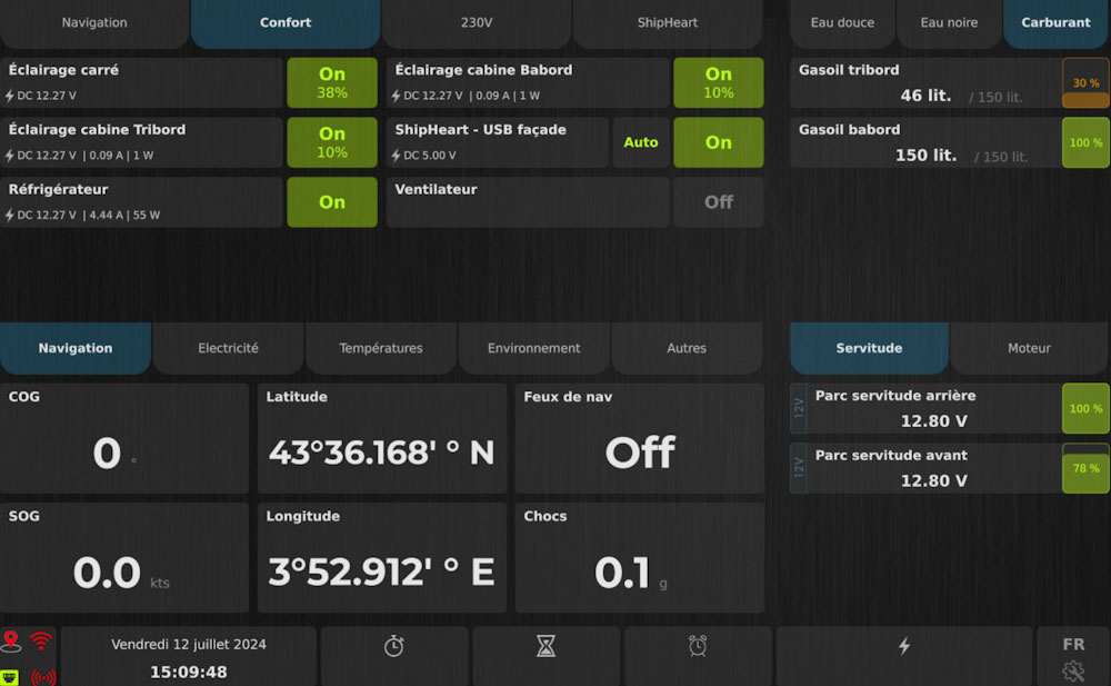
Connected to the ShipBase dashboard, ShipPower8DC controls, protects, and measures eight 12V or 24V electrical circuits.
This provides valuable measurement data for the crew and functions that ensure the vessel’s electrical safety.
Get the technical documentation for the marine DC circuit control module
The supply voltage and the current consumed by each electrical circuit are continuously measured.
This allows for:
Tripping Functions:
An Asset for Onboard Safety
To ensure the safety of the vessel and crew in all circumstances, the ‘software’ tripping system is backed by hardware protection. In case of a short circuit or abnormal overheating, the system trips automatically.
Additionally: in the unlikely event that these first two protections are inoperative, a 30A fuse is positioned on each output to ensure the vessel’s safety in all circumstances.
The ShipPower8DC module can be installed without constraints on board a vessel. The choice of location depends on the boater’s preferences.
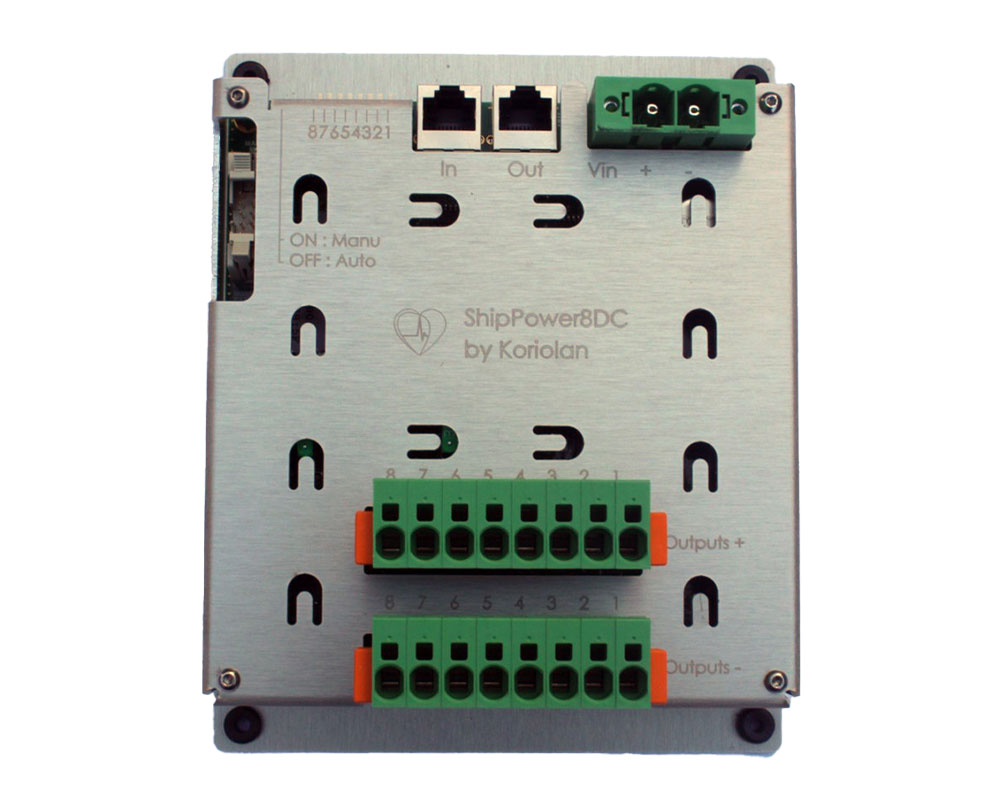
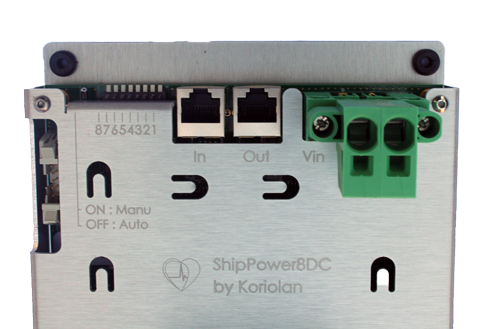
It connects in seconds and requires no configuration to be recognized by the digital switching system to which it is connected via its expansion bus (K-Bus).
Good to know: the connection cable to use is a commercial Ethernet Category 6 or higher cable. It can also be custom-made to precisely fit the required length.
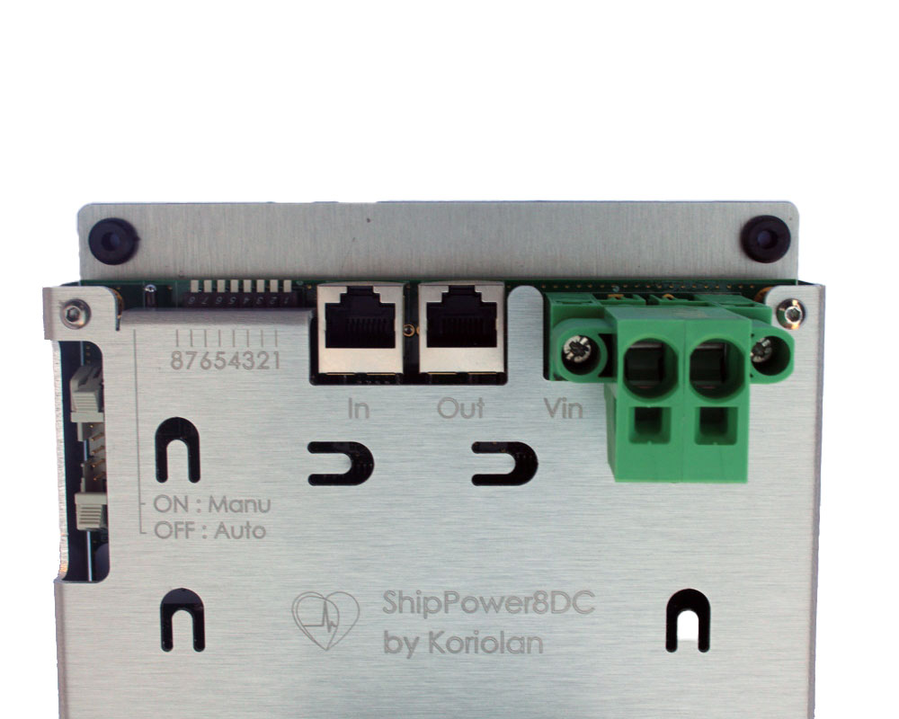
The module is inserted anywhere on the bus, regardless of the type of module located upstream (towards the boat dashboard ShipBase) and downstream. However, it is its position on the bus that distinguishes it from other modules.
The only constraint is that the cable from the upstream module is connected to its In connector. And, if it is not the last module, that the cable intended for the downstream module is connected to its Out connector.
If it is the last module, its Out connector is unused. It is then advisable to leave the rubber cap supplied with the module in place to protect it from dust and moisture ingress that could impair the subsequent connection of additional modules.
Key advantage: given its structure and the high speed of exchanges, the bus is equipped with termination resistors. However, these are automatically adjusted by ShipBase with each module addition or removal. No more risk of error or oversight!
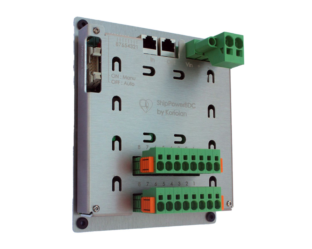
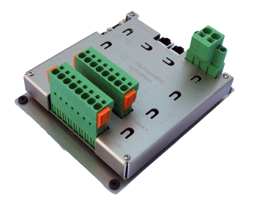
The ShipPower8DC module comes with its power connector and its two output connectors (‘OUTPUT +’ and ‘OUTPUT –’).
This two-point connector is equipped with large-section spring connections, allowing for quick connection without specific tools. Pluggable and keyed, it can be disconnected in seconds and without risk for testing or replacing a module on board the vessel.
These two connectors are identical but feature keying pins, making cross-connection (connecting the ‘OUTPUT +’ connector to ‘OUTPUT –’ or vice versa) impossible. Their spring connections allow for quick and reliable connection. The fact that they are pluggable, keyed, and locked enables fast, simple, and safe installation and maintenance.
The module is powered, optionally, by a 12V or 24V marine battery bank.
It is therefore possible to use one module on a 12V bank and one or more other modules on a 24V bank.
The control of the module’s 8 circuits is designed for bipolar mode: each circuit has a positive and a negative output controlled simultaneously. It is possible to wire each circuit in unipolar mode. In this case, the return to 0V of the battery bank occurs without passing through the module.
Each circuit is capable of supporting a continuous maximum current of 25A. However, as some equipment may require more power, especially on 12V installations, it is possible to increase this threshold to 40A. To do this, two circuits of the same module are wired in parallel and controlled as one.
Configuration takes only a few seconds: the first circuit, called the ‘main’ circuit, is created. On its configuration page, simply select the second as the ‘reinforced’ circuit.
From then on, the ‘main’ circuit has a capacity of 40A, and its tripping threshold can be set up to this value.
Note: only the ‘main’ circuit appears in the list of circuits and can be controlled.
The control mode is adjustable on each circuit’s configuration page: “On-Off”, “Progressive On-Off”, or “Dimmer”. To adapt to the load to be controlled and maximize comfort on board the vessel.
Clarification Regarding High Electrical Currents and Safety:
The module’s power connector is substantially sized to support high currents. However, to comply with the manufacturer’s recommendations across the entire operating temperature range, its capacity is permanently limited to 50A.
Thus, if the total current of all module circuits exceeds this 50A value for more than 10 consecutive seconds, the control of the highest-consuming circuit will be automatically cut off to fall back below this threshold.
In practice, this feature is not very restrictive. Indeed, circuits consuming a lot of current generally operate for short periods and, presumably, not simultaneously at their maximum current. However, it is also possible to simply limit this constraint by distributing high-consumption devices (electric toilets, pumps, autopilot, etc.) among the various ShipPower8DC modules on board.
The ShipPower8DC module automatically detects short circuits to the positive battery terminal. This error is detected when the circuit is not controlled (circuit is Off) but its output is nevertheless connected to a positive voltage, presumably the positive battery terminal.
Example: in the case of a short circuit between two theoretically independent circuits. Such a state triggers an alert for the faulty circuit and allows for fault finding before it has consequences on equipment operation or the consumption of circuits presumed to be unpowered.
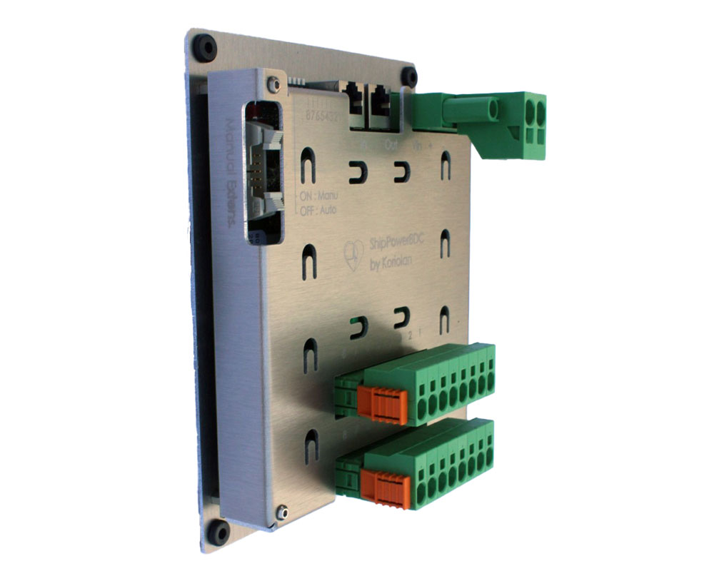
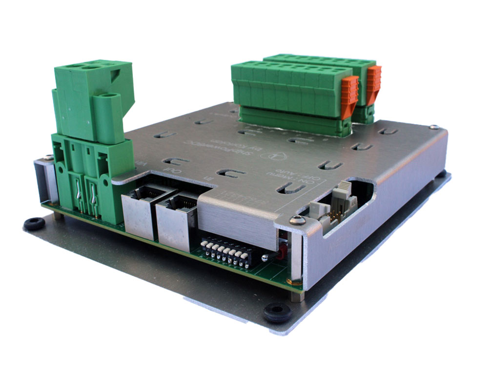
The module is also designed to control each of its circuits even in the event of system failure, regardless of the cause. For this, each ShipPower8DC includes a
And since the module can be installed in a hard-to-reach location, it includes an extension connector which allows relocating all or part of these emergency manual controls to a more easily accessible location.
Finally, if Manual mode is inadvertently activated on a module, the ShipBase dashboard display informs at a glance and even indicates the status of each circuit corresponding to its local control switch. However, in such a case, control from ShipBase is obviously not possible until the module’s switch has been repositioned to Auto…