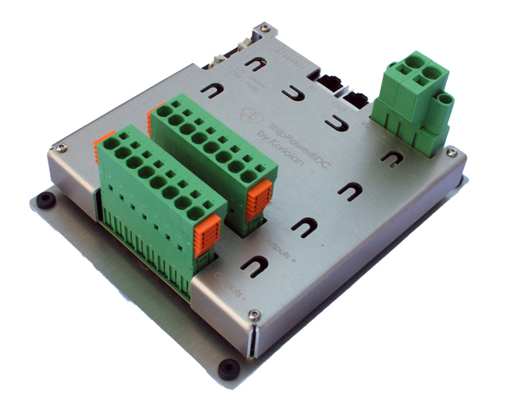
ShipPower8DC Module: Controls 8 DC Circuits
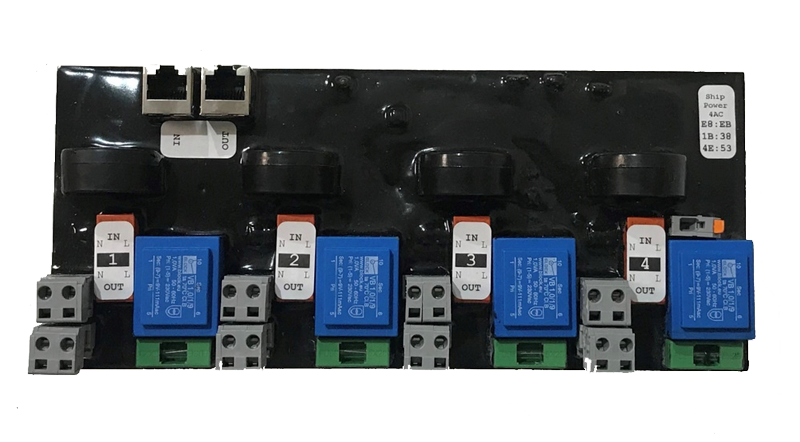
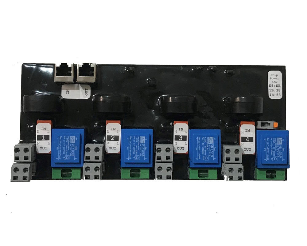
Integrated into our digital switching solution – which replaces the traditional boat electrical panel – the ShipPower4AC module controls and monitors 4 single-phase AC circuits of a ShipHeart™ system.
Obtain the technical documentation for the boat AC circuit control module
The ShipPower4AC monitors each onboard circuit:
All these measurements are visible on the ShipBase dashboard screen with their time-evolution curves.
The measurements taken by the ShipPower4AC module are also used to verify that their value remains within the defined ranges.
Otherwise, an alarm is triggered and the circuit can be automatically cut off. Similarly, the module enters a safe mode in case of an invalid ground circuit or a possible phase/neutral inversion.
Since the active parts are resin-encapsulated to prevent direct contact, the module is DIN rail mounted and connected in seconds. It requires no configuration to be recognized by the ShipBase module to which it is connected on its extension bus (K-Bus).
Good to know: the connection cable to use is a commercial Ethernet Category 6 or higher cable. It can also be custom-made to precisely fit the required length.
The module is inserted anywhere on the bus, regardless of the type of module located upstream (towards ShipBase) and downstream. However, it is its position on the bus that distinguishes it from other modules.
The only constraint: the cable from the upstream module must be connected to its In connector. And, if it is not the last module, the cable intended for the downstream module must be connected to its Out connector.
If it is the last module, its Out connector is unused. A good practice: leave the rubber cap supplied with the module in place to protect it from dust and moisture ingress that could impair the subsequent connection of additional modules.
Given its structure and the high speed of exchanges, the bus is equipped with termination resistors. However, these are automatically adjusted by ShipBase with each module addition or removal.
Connected after the protective circuit breakers, the module accepts all usual voltages:
It supports up to 32A per circuit via an external contactor (or 10A without an external contactor).
Each circuit has a female bipolar input connector – ensuring personal safety when disconnected and the circuit is live – and a male output contactor.
Both are equipped with spring connections allowing quick connection without specific tools onboard the boat. Removable and polarized, they can be disconnected in seconds and without risk for testing or module replacement.
They can also be directly coupled to bypass the module in degraded mode.
A current measurement toroid is present for each circuit. Simply slide one (and only one!) of the conductors into it before connecting it to the input connector, and the circuit wiring is complete.
Since the onboard ground is unique, only one connection to the module is required, on a quick-connect terminal block.


